Error Log
Section dedicated to projects... and mistakes
In this section you will find personal projects and hopefully inspiration for your own or ideas to find bugs and solve problems you have encountered while working on a similar case.
If this blog has help you in any way, I will be glad to hear about it.
LCD Display 1602A
16 characters, 2 lines, 16 pin display
Last update: 10th-August-2024
Introduction
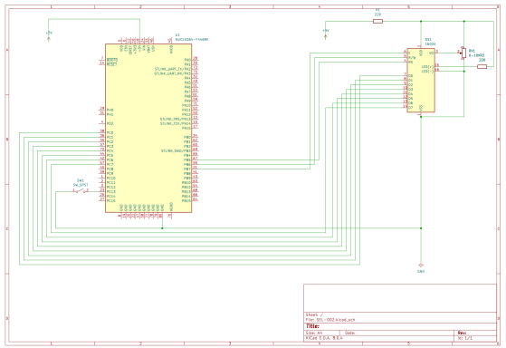
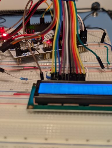
This is a simple way to control a 16-pin LCD display. The pins used in the project are:
PC13: built-in button to refresh screen
PB5, PB6 and PB7: to control the screen
PC0 to PC7: Data to write (PC7 also acts as "Busy flag".
This project is quite simple and it uses many pins of the nucleo board, so probably not the most efficient way to implement it. In any case, a good learning exercise.
Bear in mind that some pins mode will change between input and output state, so a mistake can destroy the pin. Check twice. Trust me as I have been there, done that.
Material
- Nucleo-STM32F446RE or equivalent
- LCD Display 1602A (16 pin)
- 0-10KΩ Potentiometer
- 2x220Ω Resistor
- Breadboards
- Cables
- Power supply 7V (optional)
- Power Supply 5V (optional)
- STM32CubeIDE (optional)
Description & Code
I decided to separate the code into LCDByte.h/LCDbyte.c so it makes the main.c simple and easy to understand.
At this point, LCDByte.h should be easy enough for you to understand. It is nothing more than replacing obscure numbers with more meaningful names. It will help you as well if you decide to change one or more of the used pins, for example.
[...]
#define RS (0x20) //Pin5 mask RS=0 command register, RS=1 data register
#define RW (0x40) //Pin6 mask RW=0 write , RW=1 read
#define EN (0x80) //Pin7 mask to enable data transfer
[...]
As for the functions to use:
extern void delayLCD(unsigned int ms);
extern void LCD_cmd(unsigned char comd);
extern void LCD_cmd_strt(unsigned char cmd);
extern void LCD_acsii(char data);
extern void LCD_init(void);
extern void LCD_isready(void);
extern void init_ports(void);
extern void refreshLCD(void);
This shows the importance of choosing a descriptive name for any variable and function. A word of caution. The word "extern" in a function is implicit, therefore it causes redundancy. I left it here as I used this projects for my own learning and practice, but you don't need to include it. The same can be said about the debugging code left between /* */ in the main.c file. This was the way I used to debug my program, which I understand is not the best way for most people.
Initialization of ports is included in LCD_init() by first calling to init_ports(). another interesting point is that the first time we won't be able to read the busy flag and that's why LCD_cmd_strt() is used. After this first call, LCD_cmd() is used instead. Instead of giving enough time for the LCD display to read/write data, we check D7 for a busy flag. Once this pin is low, more data can be written to the display. Therefore, it involves changing the MODE between input and output every time we need to check D7. I have probably included more delayLCD(int) than necessary, but I wanted to be sure to give each operation enough time.
Data is written in ACSII code using LCD_acsii(char) and each bit goes to one of the PC0 to PC7 (i.e. D0 to D7 in the LCD) pins. At first, I was displaying garbage. Therefore, I decided to write the letters I have left as a comment. They -except one- only differ in one bit, which helped me to realise I was adding one letter to the previous one, instead of overwriting it.
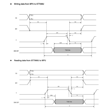
It is important to use the timing diagram from the LCD spec sheet. This will show you in what order to change pins from low to high or high to low and the minimum overlap in microseconds. Considering that my home-made delayLCD function will cause a delay of less, but close, to 1 ms when the parameter is 0, I consider it enough overlap given the highest overlap value is around 160 µs (microseconds). Feel free to play with better delay functions and timing to optimise it even further.
main.c
while(1){
const char message[32] = "SyntaxErrorLab\0";
[...]
short c = 0;
while (message[c] != '\0'){
LCD_acsii(message[c]);
c++;
if(c > 32) { return 1;}
}
/* clear LCD */
refreshLCD();
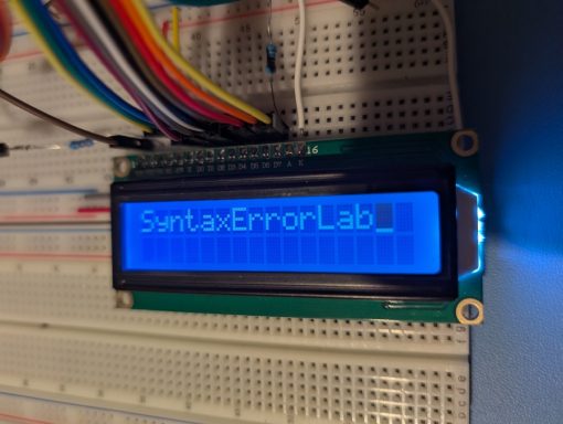
I decided to loop though the character array "SyntaxErrorLab" and include myself the '\0' termination character. I also included a "safe" statement, just in case I made a mistake so the write loop will not run for more than 32 characters.
The refresh and rewrite of the LCD is on user's demand by using board-mounted (blue) button. This functionality could have been implemented as an interrupt, but I haven't reach that part yet. Instead, it is part of the code and I made sure I left enough time to read and also avoid switch bounce effect.
Overall It has been a good learning, not only for the code writing exercise, but on how to read and interpret spec sheets. Which it can get really complex for some devices.
I know I have not explained the code line-by-line, but if it is any part you don't fully understand, send me a message and I will do my best to clarify it.
Technical spec sheets
- Nucleo board: https://www.st.com/en/evaluation-tools/nucleo-f446re.html
- https://www.openhacks.com/uploadsproductos/eone-1602a1.pdf
Other References
Mazidi, M. A., Chen, S., & Ghaemi, E. (2018). STM32 ARM Programming for Embedded Systems. MicroDigitalEd.
https://www.geeksforgeeks.org/understanding-extern-keyword-in-c/
Images LCD
Images and schematic
7-Segment Display with Nucleo-STM32
Control a 7-segment display using STM32F446RE and a shift register.
Last update: 31st-July-2024
Introduction
One of the first things to learn is how to control a 7-segment display. If fact, this type of display is no more that 7 -sometimes 8- LEDs arranged in a special configuration to be able to show numbers and some letters. It used to be a very common type of display in industrial settings, although with the lowering in cost of other type of more versatile displays they are less ubiquitous, yet still important.
One of the problems of connecting a microcontroller directly to a display is that first, it will occupy 7 of the limited number of pins available. Second, the current output through each LED will depend on how many LEDs are required for an specific digit. Hence a difference in brightness. A shift register can be used to reduce the number of pins used to control a 7-segment display. Its true benefit comes when you need to control more than one piece, as it allows for chaining.
Material
- Microcontroller: STM32F446RE (1)
- 7-Segment Display 5161AS - Common Cathode (1...)
- Shift register SN74HC595 (1 for each 7-segment display)
- 220Ω (up to 470Ω resistors) (7x for each display)
- Breadboards
- Cables
- Power supply 7V (optional)
- Power Supply 5V (optional)
- STM32CubeIDE (optional)
Description & Code
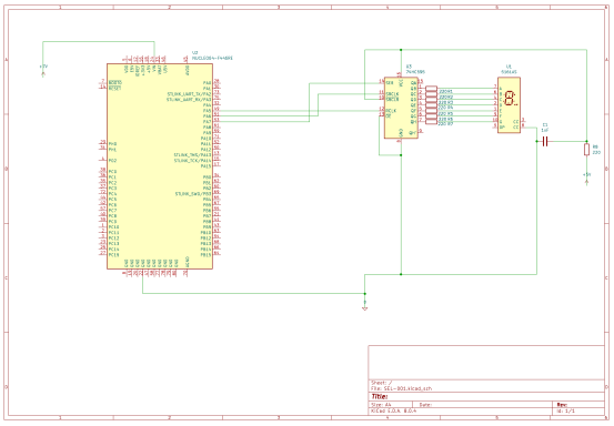
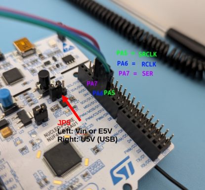
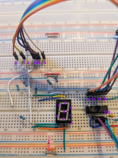
First, follow the schematic and the photos to connect all the components. I decided to use separate power supplies for the Nucleo board and for the shift register SN74HC595. The Nucleo board is powered at 7V. The is no need to include a resistor because the current provided by the power supply is within the limits of the board. Bear that in mind. However, I inserted a resistor for the 5V voltage supply. All said, I did not put much thought into protecting the components in this circuit. One important note if you use more than one power supply is to ensure all the components have the same ground reference.
The Code (available in the Github link below). You have probably noticed that I did not used HAL (Hardware abstraction Layer), nor I will do in many projects. The reason to learn STM32 was to "know how things work" and avoid the abstraction provided by the Arduino -C based- language. Although it is welcome to get things done, it keeps me from learning what I want to learn.
The code is based on the Arduino code created by Mario (check his tutorial video because it is really well explained). However, there are two main obstacles in that video. First, it is created for an Arduino board. Second, the code contains 2 bugs I will explain later.
main.h:
I define names for the HEX codes to be used with the registers. They start with "JTM" to avoid conflict with HAL names:
/* USER CODE BEGIN Private defines */
#define JTM_GPIOA_CLK_EN (1)
#define JTM_CLEAR_PA5_6_7 (~0x0000FC00)
#define JTM_OUTPUT_PA5_6_7 (0x00005400)
#define JTM_BSRR_SRCLK_PA5_HI (0x00000020)
#define JTM_BSRR_SRCLK_PA5_LO (0x00200000)
#define JTM_BSRR_RCLK_PA6_HI (0x00000040)
#define JTM_BSRR_RCLK_PA6_LO (0x00400000)
#define JTM_BSRR_SER_PA7_HI (0x00000080)
#define JTM_BSRR_SER_PA7_LO (0x00800000)
This codes will have the 1s and 0s in the right place for the operation to be done and a more descriptive name. In that way, if you need to find a bug or read it after you have forgotten what it means, it will be easier to find.
main.c
We start by defining a map between a digit and the segments to be lit in the display. Therefore the double array is 10 digits and each of the digits has 8 bits corresponding each of the 7-segment display LEDs. I found here the first bug on digit 1. For example, digit '1' requires segments 'b' and 'c' to be lit, so the array is [0, 0, 1, 1, 0, 0, 0, 0] = [h, a, b, c, d, e, f, g]. This bits are pushed to the shift register from the LSB (least significant bit) to the MSB (most significant bit).
Next, we declare two user functions. delayMs will be used to introduce a delay without using HAL's function. For 16 MHz the number I found the best is 3200 cycles, but always check with an oscilloscope if timing is critical. The second function will simplify the code to display a digit. Both functions take an integer as an argument. I have passed it as value, not reference.
delayMs is not more than a nested loop that is will take approximately 'n' milliseconds to complete. displayDigit will be explained in more details below.
Before entering the infinite loop, we set up the clock for GPIOA, clear the mode of Pins 5, 6 and 7 and finally set up those pins as 'output' pins. A pin is set up as an output pin by writing '01' to its MODER register. We do that with the hexadecimal numbers below. MODER register is a 32-bit register and every 2 bits we write to a new pin. I recommend you to look up this information in the datasheet or in the referenced book below for more details. Notice that the tilde '~' before an hex number it changes 0s to 1s and vice versa. To write to these registers without affecting the other bits the bit-wise and (&) and or (|) operators are used. These operators perform a logic 'and' or a logic 'or' but bit by bit. Hence &= will clear all the bits where the bit at that position is 0 and leave unchanged those with bits with value 1.
RCC->AHB1ENR |= JTM_GPIOA_CLK_EN; // 0x1 = 0b1
GPIOA->MODER &= JTM_CLEAR_PA5_6_7; // ~0x0000FC00 = 0b1111_1111_1111_1111_0000_0011_1111_1111
GPIOA->MODER |= JTM_OUTPUT_PA5_6_7; // 0x00005400 = 0b0000_0000_0000_0000_0101_0100_0000_0000
Now the never ending loop: There is a for loop to count from 0 to 9. Inside this loop, we use the user-defined function displayDigit to send the required digit to the shift register and hence to the 7-segment display. Now, the most important part of this code, the displayDigit function.
GPIOA->BSRR = JTM_BSRR_RCLK_PA6_LO; // RCLK (aka STCP) Low. Do not send to display
// update all 8 bits from LSB to MSB
for(int d = 7; d >= 0; d--){
GPIOA->BSRR = JTM_BSRR_SRCLK_PA5_LO; // SRCLK (aka SHCP) Low. Ready to prepare bits
if(digits[Digit][d] == 1) { GPIOA->BSRR = JTM_BSRR_SER_PA7_HI; } // SER (aka DS) High. Write a '1'
else { GPIOA->BSRR = JTM_BSRR_SER_PA7_LO; } //SER (aka DS) Low. Write a '0'
GPIOA->BSRR = JTM_BSRR_SRCLK_PA5_HI; // SRCLK (aka SHCP) High. Stop writing bits
}
GPIOA->BSRR = JTM_BSRR_RCLK_PA6_HI; // RCLK (aka STCP) High --> send data to shift register
BSSR is a register in which the bits 31 to 16 are to set pins 15 to 0 to '0' (reset or low), while bits 15 to 0 are to set the value of pins 15 to 0 to '1' (set or high). Therefore, bitwise logic operations are not necessary and we can write the value of pins 5, 6 and 7 directly.
Once all the code is written and syntax errors corrected, build and debug. I will dedicate another post to how to create a new project, build and flash to memory using STMCubeIDE on Windows 10. At the moment (2024) it does not work very well on Ubuntu 24.04 because for some reason I don't understand ST Microelectronics ® continue to rely on Python 2.
I know I could have gone into more detail, but if you have any question or problem, let me know what and how, or send me the link to your tutorial and we can tell other makers / developers.
Technical spec sheets
- 7-Segment display: http://www.xlitx.com/datasheet/5161AS.pdf
- Shift Register: https://www.ti.com/lit/ds/symlink/sn74hc595.pdf
- Nucleo board: https://www.st.com/en/evaluation-tools/nucleo-f446re.html
Other References
Mazidi, M. A., Chen, S., & Ghaemi, E. (2018). STM32 ARM Programming for Embedded Systems. MicroDigitalEd.
Mario's Ideas (Youtube): https://youtu.be/QI1IJLB42G8?si=bLfExA-yZwqyeFAG
Images
Completed Project and details.
©Copyright. All rights reserved.
We need your consent to load the translations
We use a third-party service to translate the website content that may collect data about your activity. Please review the details in the privacy policy and accept the service to view the translations.
